

S5 for Windows® and S7 for Windows®
The combined version of S5 for Windows® and S7 for Windows® contains all functionality of both tools in one application, so a single package covers the SIMATIC S5 and S7-300/S7-400 families.
Already running V6? You do not need new licenses. The update to Version 7 is free. Checkout requires both of your existing serial numbers, S5W and S7W.
Windows 11 compatible. Both S5 for Windows® V7 and S7 for Windows® V7 run on Windows 11 (64 bit).
S5 Programming
S5 for Windows® provides the tools for creating, modifying, testing and documenting programs for programmable logic controllers. It is designed for programming the Siemens SIMATIC S5 family with STEP 5, using Function Block Diagram (FBD), Ladder Diagram (LAD) and Statement List (STL) as presentations. Existing S5 programs can be edited directly with no import or export step. The software is compatible with the original Siemens programming unit, and the S5 Doctor functions are integrated for automatic troubleshooting.
Editor and symbolic tables
- Integrated editor for creating and editing symbolic tables, with search, replace on any criteria, rewiring and a built in syntax check.
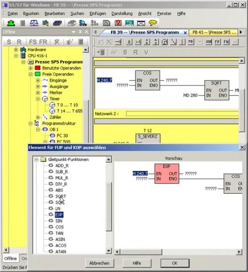
- Multiple segment editor for statement lists, function block diagrams and ladder diagrams, including complex functions, built for both mouse and keyboard use.
- Cross references and the corresponding symbol files are shown with the correct addresses, and the symbol file can be edited in the same window.
- Allocation of new addresses with syntax check is integrated.
- The Windows clipboard can be used for program or configuration changes anywhere in the project.
- Statement lists can be converted to function block diagram or ladder diagram wherever they are displayable, and FBD or LAD can always be displayed as a statement list.
Status display and communication
Multiple segments can be shown in the status display across statement list, function block diagram and ladder diagram. The CPU status function reports on the interrupt stack, block stack and system data. S5 for Windows also allows COM packages to be called, and communication to a PLC can be established using a USB adaptor.
G5 step sequence programming
G5 for Windows® step sequence programming, now included within S5 for Windows, is a tool for programming sequencer control inside a STEP 5 program. A step sequence programmed in a step sequence block (SB) is made of steps and transitions, where the transition logic enables the following step. The graphical editor supports linear sequences, alternative branching, simultaneous branching and jumps.
- Step types: steps are displayed as boxes and differentiated as initial, permanent or selective. The initial step starts the sequence unconditionally, a permanent step always executes even when the step flag is inactive, and a selective step is skipped when the step flag is inactive.
- Transitions: displayed as lines. The following step runs only when the transition logic is true, and a simultaneous branch can open up to eight further steps.
- Timing: every step except the initial step can be assigned a waiting time (delay timer) or a monitoring time (watchdog).
- Compatibility: compatible with the Siemens GRAPH 5 and GRAPH 5/II packages, so the standard Siemens function and step blocks are required (FB70/71 with SB0, FB72 with SB2, FB73 with SB3).
- Working view: the logic of the selected step or transition is shown in a separate resizable window and can be edited in LAD, CSF or STL, with the symbolic library available at the same time.
- Display: step box size adjusts to the comments used, the status display matches the editor layout, and active or corrupted steps are specially indicated.
S7 Programming
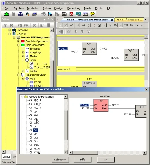
To program the Siemens S7-300 and S7-400 series efficiently, IBHsoftec provides S7 for Windows®. It can be combined with S5 for Windows or run standalone, and the complete S7 instruction set is implemented in Statement List (STL), Function Block Diagram (FBD) and Ladder Diagram (LAD).
Interface and online functions
All online functions are implemented. The operating concept in version 7 was rebuilt around current thinking in operator guidance: block lists and symbolic tables can be arranged freely, moved from the main window onto a second screen, and hidden automatically to free up screen space. Module parameter presentation has been adjusted to match. All installed interfaces capable of connecting to a PLC are shown in the online view.
Status view
The entire S7 instruction set can be shown in status view in STL, and status operation is also available in FBD and LAD. Variable views and symbolic tables are integrated into the status window.
Project handling
- All STEP 7 projects can be edited directly with no import or export step, and archived STEP 7 projects can be opened directly.
- Password protection can block all write access to the PLC.
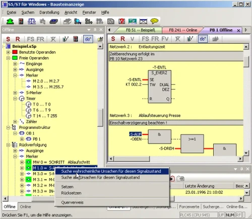
- Signal (operand) traceability, cross reference across complete I/O modules, and hardware or module diagnostics are supported.
- Print preview and forcing of operands are included.
- Conversion from S5 to S7 programs has been optimized.
- Complete S7 projects can be saved to a memory card, depending on the CPU.
Simulation, comparison and automated debugging
Version 7 includes S7 simulation and the block comparison tool (BlockDiff), and the S7 Doctor functions for automated troubleshooting are integrated. S7 for Windows performs fully automated debugging in the running PLC program: it carries out the tasks a classical debugging session would require and returns the reason for the stop in plain text. Unlike conventional diagnostic tools, it needs no special adaptation of the PLC program.
Hardware configuration and PROFIBUS
The hardware configuration handles module parametrizing, address allocation and PROFIBUS configuration. Clicking a module in the configuration opens a dialogue for its parameters, and changes made in the detail window of a module or CPU are clearly marked so nothing is altered unintentionally before saving.
- The hardware catalogue includes Siemens PROFIBUS components plus compatible components from other manufacturers, and can be extended with GSD files.
- Hardware configurations in existing STEP 7 projects can be read and edited, and configurations can be read and edited directly from a PLC as well as created offline.
- Module diagnostic functions are integrated for quick debugging.
- The hardware catalogue is updated constantly for the latest modules, and updates are free via the internet.
Connecting to your PLC
The software needs a physical connection to the controller, and the right one differs between the two PLC generations.
For SIMATIC S5
- IBH USB-S5-Adaptor – connects a PC USB port to the 15 pin AS511 programming port. The straightforward choice for working at the panel with a modern laptop.
- IBH Link S5++ – an Ethernet converter that puts the S5 PLC on your network over standard TCP/IP, for remote maintenance through a router or VPN.
- IBH S5 Current Loop Converter – the serial option, for a PC with a true COM port where the PLC supplies the 20 mA loop current.
For SIMATIC S7-300 and S7-400
- USB-S7 Adaptor MPI, DP, PPI – plugs into the MPI programming socket on the CPU, or any node on the MPI bus, and connects to your laptop over USB.
- IBH Link S7++ – an Ethernet to PROFIBUS gateway that replaces a Siemens CP and SIMATIC NET, with programming and PLC to PLC communication over TCP/IP.
- IBH Link S7++ HS – the same capability in a DIN rail mount housing with external 24 V supply, for permanent installation in the cabinet.
Diagnostics and analysis tools
The following diagnostic features are integrated into S5 for Windows and S7 for Windows alike.
OsciCAM®
Analyze motion processes by synchronizing previously recorded video with process signals. Recorded video plays in sync with process signals and a time stamped record of PLC block status.
Statusrecorder
Explore dynamic procedures by reviewing block status frame by frame after the fact. The Statusrecorder logs block status with a time stamp and lets you switch between STL, CSF and LAD during review.
Integrated oscilloscope
The oscilloscope feature extends the diagnostic capability of the programming system. Dynamic processes are monitored and analyzed in an integrated screen modeled on an oscilloscope front panel. Pointing at I/O signals with a virtual test probe is enough to monitor several signals at once, and recording can be stopped at any point to investigate the timing of a machine fault.
Beyond I/O signals, the state of local variables at a defined position in program execution can be watched by pointing the test probe at the variable in block status, which is only possible because the oscilloscope is built into the programming system. Recorded data can be saved for later investigation, for archiving, or to send by email.
Also available
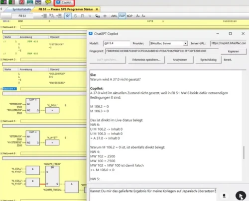
- S5/S7 AI for Windows® – this same combined package plus an AI copilot that analyzes your open project and live PLC data, and answers troubleshooting questions in plain language. Particularly useful on older systems where the documentation is incomplete.
- S5/S7 AI for Windows® upgrade – if you already hold a V7.x license, add the AI copilot to it here rather than buying the full package again.
Only need one PLC generation? The S5 for Windows® and S7 for Windows® programming systems are also sold separately.