Frequently Asked Questions - SLIO
SLIO
Which software is required for the 053-1DN00 DeviceNet module?
How to configure a VIPA SLIO 015 CPU in Step 7 SIMATIC Manager?
How to configure a VIPA SLIO 014 CPU in Step 7 SIMATIC Manager?
How to assign addresses in the hardware configuration?
How to save the module parameters into the flash of the Ethernet/IP coupler?
SLIO
Which software is required for the 053-1DN00 DeviceNet module?
The module can only be parameterized with RSNetWorx from Rockwell Automation.
How to configure a VIPA SLIO 015 CPU in Step 7 SIMATIC Manager?
This How-To article describes the hardware configuration of a VIPA SLIO 015 CPU in Step 7 SIMATIC Manager.
HTD_SLIO_001_EN_Hardware_Configuration_SLIO_CPU_015_using_SIMATIC_Manager_2014-01.pdf (4 MB)
How to configure a VIPA SLIO 014 CPU in Step 7 SIMATIC Manager?
This How-To article describes the hardware configuration of a VIPA SLIO 014 CPU in Step 7 SIMATIC Manager.
HTD_SLIO_001_EN_Hardware_Configuration_SLIO_CPU_014_using_SIMATIC_Manager_2014-01.pdf (3 MB)
How to assign addresses in the hardware configuration?
CAUTION!With PROFIBUS maximum 244 Byte and maximum 64 SLIO modules.
The description "Input data size" in the catalogue relates to the periodic exchanged data. The data required for parameterization are here not mentioned. But they must be considered in the design of the assembly with respect to the maximum limit of 244 bytes.
Background: During the initialization of the coupler the parameter data of all assemblies will sent in one telegram to the coupler. Therefore, the sum of all parameter must not exceed the maximum limit of 244 bytes.
Example 1: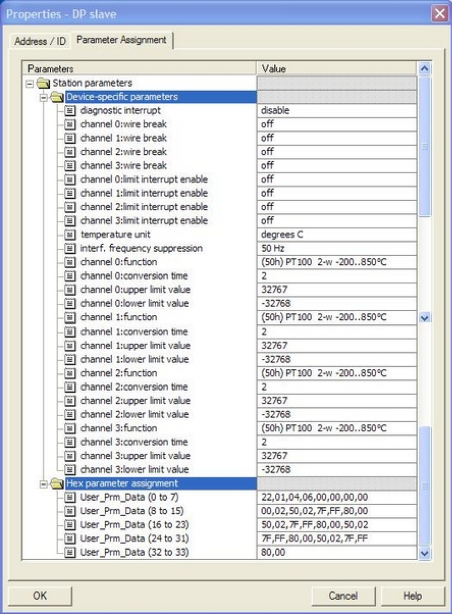
Image 1:Analog input module 031-1BD80 AI 4x16 Bit, RTD
During the projection it must be calculated with 34 Byte per assembly. ->A maximum of 7 modules is possible
Example 2: 
Image 2: The assembly 031-1LD80 AI 4x16 Bit, RTD with less parameter options.
There are only 12 bytes of address range for the parameterization required -> A maximum of 20 modules is possible.
Note: With PROFINET - coupler the number of connected SLIO-cards is limited of 64. The number of parameter data is irrelevant.
How to save the module parameters into the flash of the Ethernet/IP coupler?
With Save "Configuration" the parameter is written permanently, this means, even after power failure the changed parameters of the connected modules are remained unaffected. Currently only the modified parameters are stored and displayed permanently after the coupler was disconnected and a connection has been established after the restart.
Procedure: Call website coupler. Remove the scanner connection, if one exists. Select modules of which the parameters have to be changed. Change parameters. Confirm with SAVE - parameters remain stored in volatile memory. Switch to Device, select "Configuration"
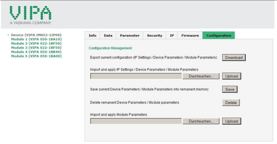
Press the "Save" button
Confirmation: Configuration information for device and modules has been saved
Make coupler de-energized. Connecting the scanner after restart. After successful connection, the changed parameters are stored visibly in the modules. It is important to ensure after re-connection that the scanner does not overwrite the configuration data again, if the Web configuration should remain valid.
Need help with something else? Submit a ticket and our support team will be happy to assist you.