Frequently Asked Questions - 300S
300S/300V
Does SPEED7 support the Siemens module 6ES7 338-4BC00-0AB0?
How to set up S7 connection in TIA portal?
How to set up a S7 connection between a Siemens OPC-server and a VIPA S7-300 series PLC?
Do VIPA NET CPUs support clock synchronization?
How many PROFIBUS-DP slaves could be configured on a 31XC in Simatic manager?
What are the differences between SPEED7 CPUs and 300V CPUs?
Is an MMC card required for SPEED7 CPUs?
RS485 Communications Using a VIPA 300S CPU
How to configure a VIPA 317NET CPU with Speed-Bus Communication Processors in WinPLC7?
How to configure a VIPA 314ST/DPM CPU in WinPLC7?
How to configure EtherCAT Hardware using Step 7 SIMATIC Manager?
How to configure 300S CPU Hardware?
How to configure 300S I/O Module Hardware?
How to configure 300S Misc. Module Hardware?
300S/300V
Does SPEED7 support the Siemens module 6ES7 338-4BC00-0AB0?
Yes, this module could be operated together with VIPA CPUs.
How to set up S7 connection in TIA portal?
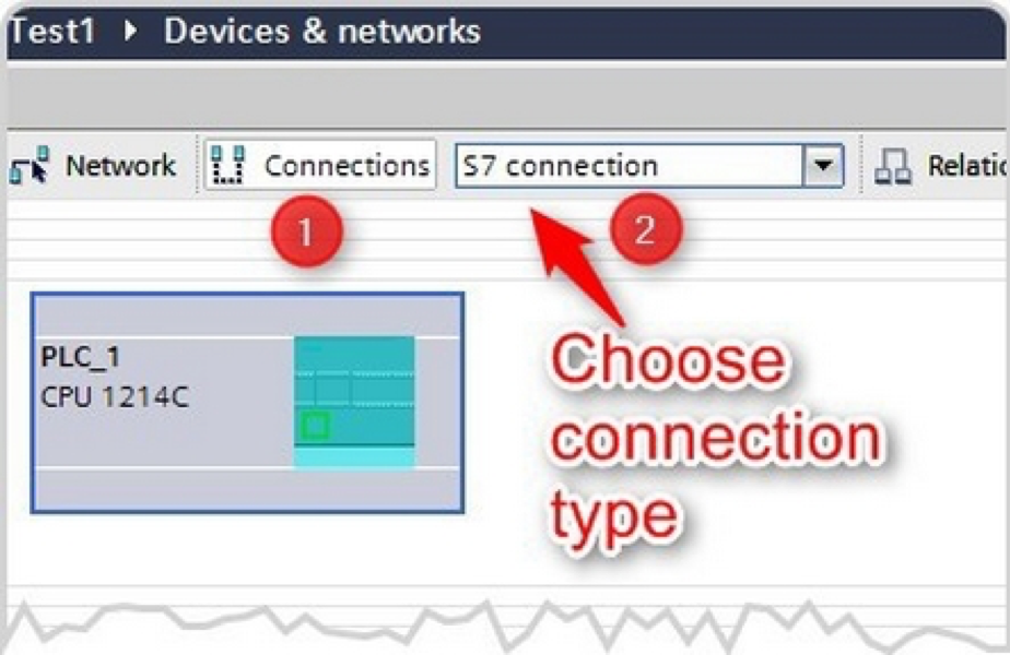
In the device and network overview you are able to setup network connection between the devices in your project. After choosing a connection type you can set all needed parameters in the properties area.
Choose the device and network overview to show all configured devices of your project.
Actions:
- Press connections
- Choose S7 connection
Specified connection: Choose an interface of your device and drag and drop the connection line to the interface of the 2nd device.
Unspecified connection:Pull away the connection line from your device by holding the left button of your mouse and drop them back into the same interface.
∫ = Symbol must appear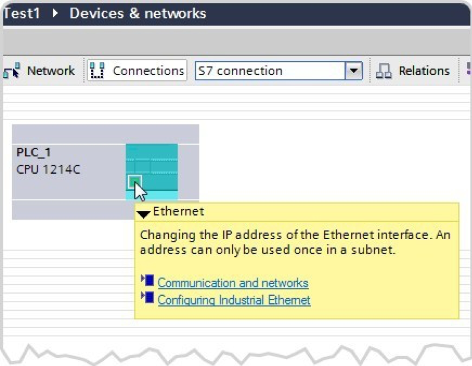
Double click the left button of your mouse, inside of the Ethernet interface that the S7 connection will be generated.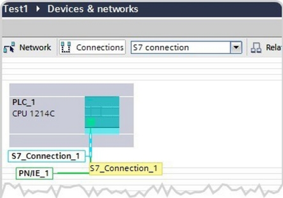
Mark the S7 connection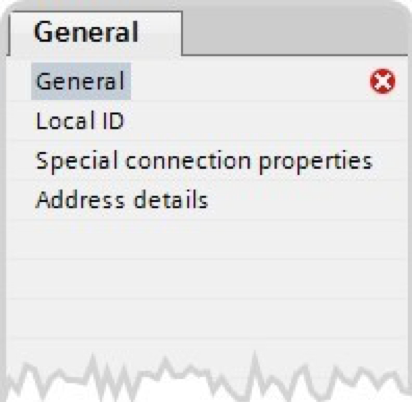
How to set up a S7 connection between a Siemens OPC-server and a VIPA S7-300 series PLC?
1. Configuration of the PC station
1.1 Set in the Simatic Manager to create a new project with"File -> New"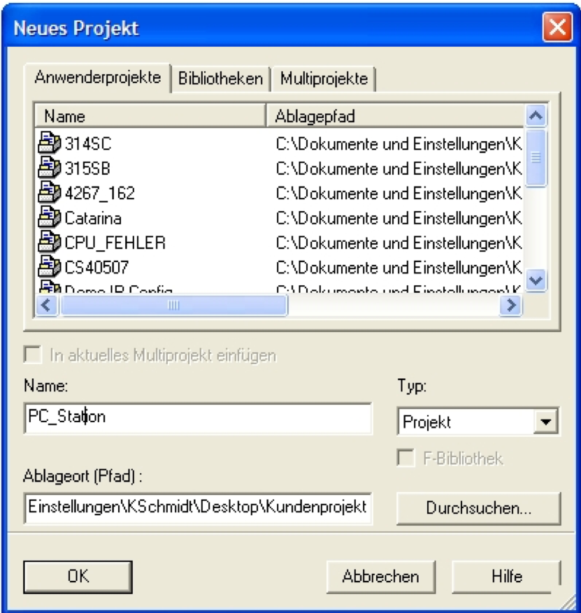
Figure 1: Assign a project name
Confirm the input of the project name (in the example: "PC_Station") with OK.
1.2 Adding PC Station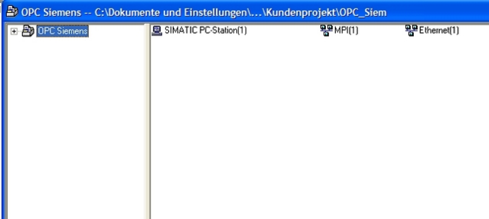
Figure 2: Adding PC Station
Add a PC station with the menu item"Insert -> Station -> SIMATIC PC Station".
1.3 Open the hardware configuration of the PC station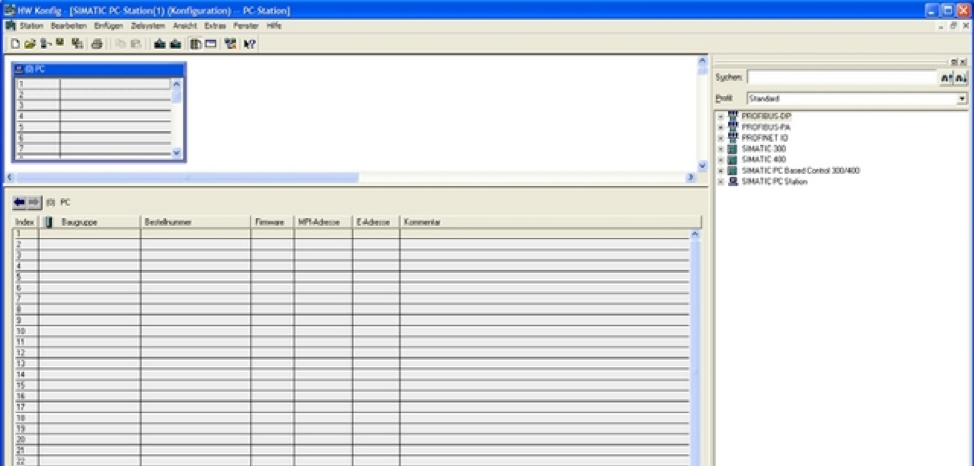
Now open the hardware configuration of the PC station. For this, you have to select the PC station, then right mouse click ->"Open Object". If the hardware catalog should not exist, then open it now.
1.4 Selection of modules via the hardware catalog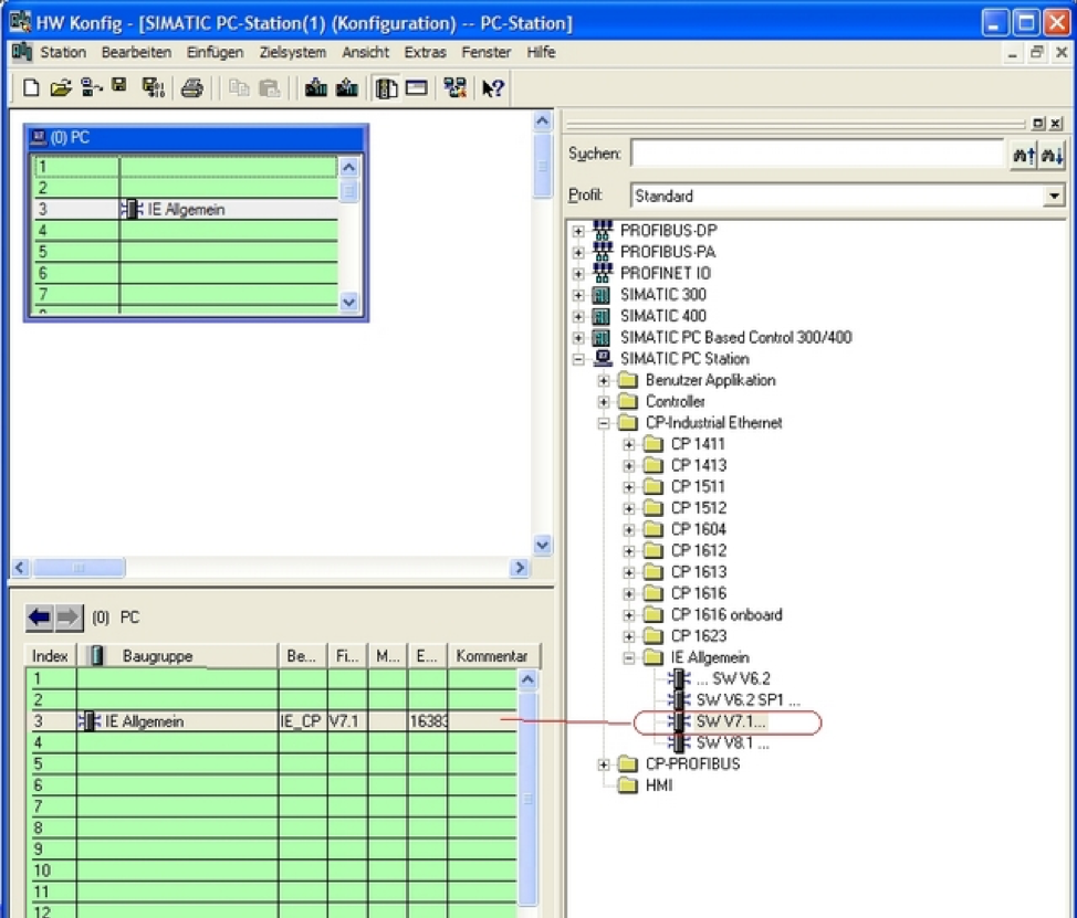
Now place your PC modules in the rack and connect them and assign an IP address. The IP address you assign is the address for your PC.
1.5 OPC server project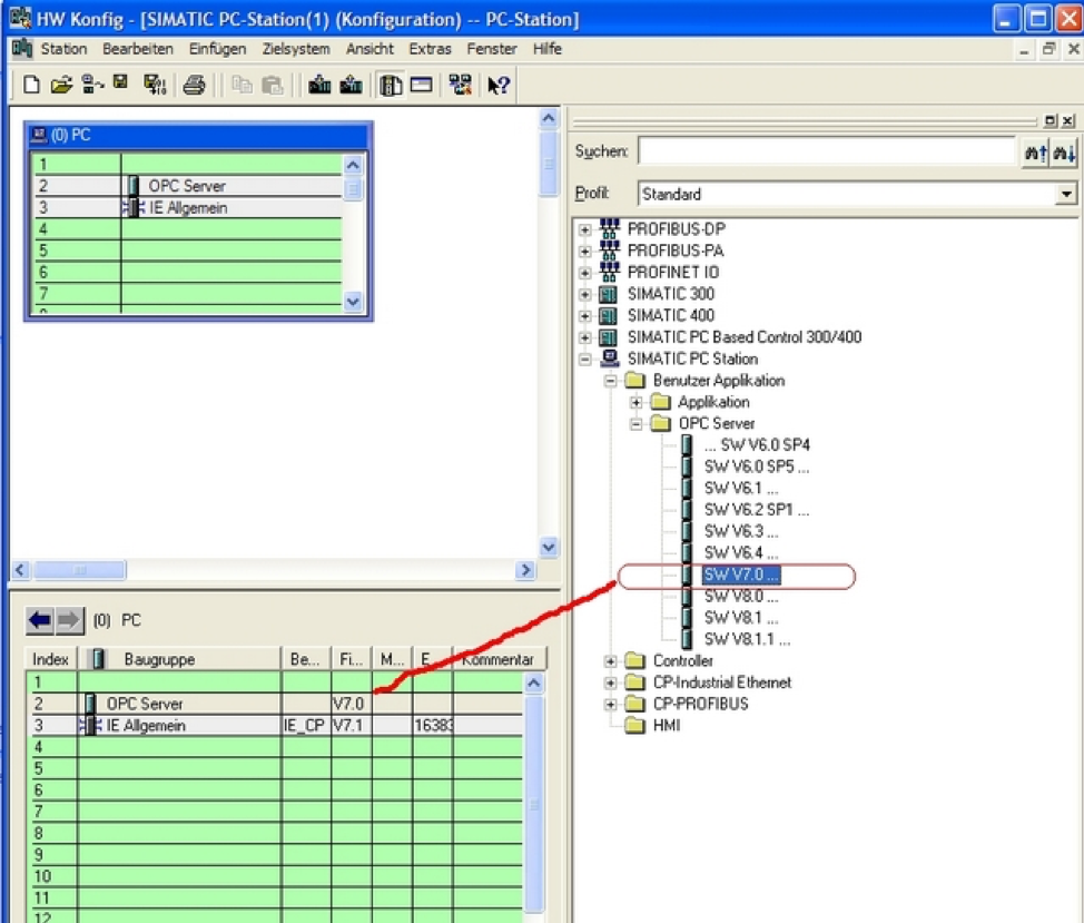
Select the OPC server in the hardware catalog and drag and drop into any available slot. Now open the program"NetPro"and place an unspecified S7 connection.
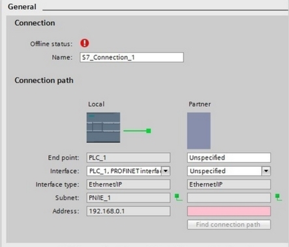
1.6 Object attributes of the S7 connection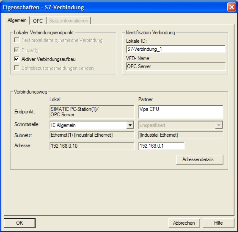
As the connection is now created "unspecified", you have to enter the IP address of the partner.
1.7 Address details of the S7 connection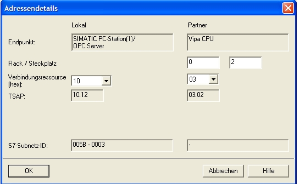
Please fill in the CPU slot of the Simatic S7 control partner.
2. Software "Configuration Editor"
2.1 Configuring and loading via "Import Station"
Open the software "Configuration Editor" which you can find as an icon on your desktop
Click the "Import Station" button and confirm the next window with "Yes".
2.2 Find the XDB file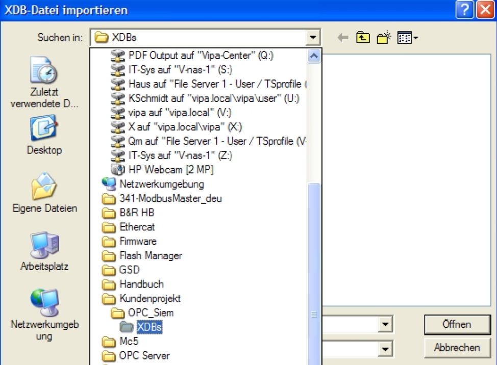
Enter the path where the XDB file can be found via the browser window. The XDB is always created in the project from Step 7. (See Figure 1: Creating a project)
2.3 Information from the XDB file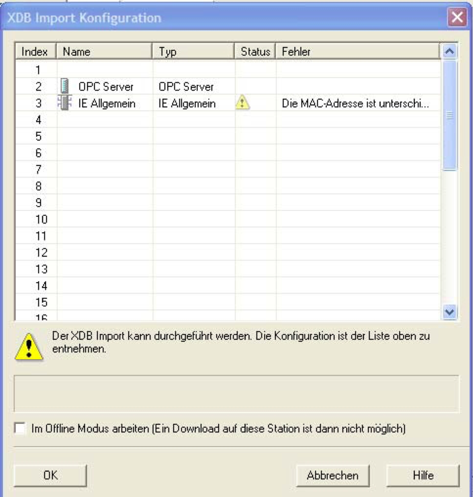
Confirm this window with "OK". The import is now completed, and the project engineering is loaded.
3. Start the OPC-Scout
3.1 Start the OPC-Scout by "Start> SIMATIC> SIMATIC NET> OPC Scout"
3.2 Connect with the OPC-Server and create a group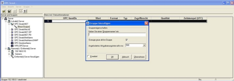
Connect to the OPC server by performing a double click on "OPC.SimaticNet". Enter a suitable group name in the displayed dialog and confirm with OK.
3.3 OPC Navigator
By repeating the double-click on the link and "objects" the tree with the possible objects appears which can be accessed.
Do VIPA NET CPUs support clock synchronization?
Yes, when the 6GK7 343-1EX11 Ethernet CP is configured.
Is it possible to create an MPI connection with XPUT & XGET between a SPEED7 CPU and a Siemens S7-200?
It is not possible to create an MPI connection between a Speed7 CPU and a Siemens S7-200.
How many PROFIBUS-DP slaves could be configured on a 31XC in Simatic manager?
In Simatic Manager, only 32 slaves can be configured. In WinPLC7, up to 124 slaves can be configured.
What are the differences between SPEED7 CPUs and 300V CPUs?
Speed7 CPUs: 4 Accumulator Levels, integrated PG/OP Ethernet Port. 100V, 200V, 300V CPUs: 2 Accumulator Levels
Is an MMC card required for SPEED7 CPUs?
No, the program will be stored in RAM for up to 30 days without power. An MMC should be used to back up the program if power is to be lost to the CPU for over 30 days.
RS485 Communications Using a VIPA 300S CPU
This How-To article covers how to configure RS485 communications on a VIPA 300S CPU.
HTD_300S_002_ENG_Configuration_with_RS485_2012_01.pdf (300 KB)
How to configure a VIPA 317NET CPU with Speed-Bus Communication Processors in WinPLC7?
This How-To article describes the hardware configuration of a VIPA 317NET CPU with Speed-Bus Communication Processors in WinPLC7.
HTD_300S_002_ENG_Hardware_Configuration_of_the_CPU_317NET_with_external_CPs_on_Speed_Bus_2012_08.pdf (300 KB)
How to configure a VIPA 317NET CPU with Speed-Bus Communication Processors in Step 7 SIMATIC Manager?
This How-To article describes the hardware configuration of a VIPA 317NET CPU with Speed-Bus Communication Processors in Step 7 SIMATIC Manager.
HTD_300S_002_ENG_Hardware_Configuration_of_the_CPU_317NET_with_external_CPs_on_Speed_Bus_with_SIMATIC_Manager_2012_08.pdf (600 KB)
How to configure a VIPA 314ST/DPM CPU in WinPLC7?
This How-To article describes the hardware configuration of a VIPA 314ST/DPM in WinPLC7.
HTD_300S_002_ENG_HW_Configuration_of_the_CPU_314STDPM_with_WinPLC7_2012-08.pdf (90 KB)
How to configure EtherCAT Hardware using Step 7 SIMATIC Manager?
This How-To article describes how to use the VIPA EtherCAT Manager within Step 7 SIMATIC Manager to configure a VIPA EtherCAT CPU.
HTD_300S_001_EN_EtherCAT_Communication_with_CPU_300S_using_SIMATIC_Manager_2013-12.pdf (3 MB)
How to configure 300S CPU Hardware?
When programming VIPA 300S CPUs using STEP 7 V5.5 or TIA Portal, please use the following chart to determine the proper CPU hardware configuration.
| VIPA Part Number | Hardware Configuration |
|---|---|
| 312-5BE13 | 6ES7 312-5BE03-0AB0 V2.6 |
| 313-5BF13 | 6ES7 312-5BF03-0AB0 V2.0 |
| 313-6CF13 | 6ES7 313-6CF03-0AB0 V2.6 |
| 314-2AG12 | 6ES7 318-2AJ00-0AB0 V3.0 |
| 314-2AG13 | 6ES7 318-2AJ00-0AB0 V3.0 |
| 314-2BG03 | 6ES7 318-2AJ00-0AB0 V3.0 |
| 314-6CF02 | 6ES7 318-2AJ00-0AB0 V3.0 |
| 314-6CF03 | 6ES7 318-2AJ00-0AB0 V3.0 |
| 314-6CG13 | 6ES7 314-6CG03-0AB0 V2.6 |
| 315-2AG12 | 6ES7 318-2AJ00-0AB0 V3.0 |
| 315-2AG13 | 6ES7 317-2AJ10-0AB0 V2.6 |
| 315-4EC12 | 6ES7 315-2EH14-0AB0 V3.2 |
| 315-4NE12 | 6ES7 318-2AJ00-0AB0 V3.0 |
| 315-4NE13 | 6ES7 318-2AJ00-0AB0 V3.0 |
| 315-4PN12 | 6ES7 315-2EH13-0AB0 V2.6 |
| 315-4PN33 | 6ES7 315-2EH13-0AB0 V2.6 |
| 317-2AJ12 | 6ES7 318-2AJ00-0AB0 V3.0 |
| 317-2AJ13 | 6ES7 318-2AJ00-0AB0 V3.0 |
| 317-4EC12 | 6ES7 317-2EK14-0AB0 V3.2 |
| 317-4NE12 | 6ES7 318-2AJ00-0AB0 V3.0 |
| 317-4NE13 | 6ES7 318-2AJ00-0AB0 V3.0 |
| 317-4PN12 | 6ES7 317-2EK13-0AB0 V2.6 |
How to configure 300S I/O Module Hardware?
When programming VIPA 300S CPUs using STEP 7 V5.5 or TIA Portal, please use the following chart to determine the proper hardware configuration.
| VIPA Part Number | Hardware Configuration |
|---|---|
| 321-1BH01 | 6ES7 321-1BH02-0AA0 |
| 321-1BH70 | VIPA SPEED-Bus GSD File |
| 321-1BL00 | 6ES7 321-1BL00-0AA0 |
| 321-1FH00 | 6ES7 321-1FH00-0AA0 |
| 322-1BF01 | 6ES7 323-1BF01-0AA0 |
| 322-1BH01 | 6ES7 322-1BH01-0AA0 |
| 322-1BH41 | 6ES7 322-1BH01-0AA0 |
| 322-1BH60 | 6ES7 323-1BL00-0AA0 |
| 322-1BH70 | VIPA SPEED-Bus GSD File |
| 322-1BL00 | 6ES7 322-1BL00-0AA0 |
| 322-1HH00 | 6ES7 322-1HH01-0AA0 |
| 322-5FF00 | 6ES7 322-5FF00-0AA0 |
| 323-1BH00 | 6ES7 323-1BH00-0AA0 |
| 323-1BH01 | 6ES7 323-1BH01-0AA0 |
| 323-1BH70 | VIPA SPEED-Bus GSD File |
| 323-1BL00 | 6ES7 323-1BL00-0AA0 |
| 331-1KF01 | 6ES7 331-1KF01-0AB0 |
| 331-7KF01 | 6ES7 331-7KF01-0AB0 |
| 331-7KB01 | 6ES7 331-7KB01-0AB0 |
| 331-7AF70 | VIPA SPEED-Bus GSD File |
| 331-7BF70 | VIPA SPEED-Bus GSD File |
| 332-5HB01 | 6ES7 332-5HB01-0AB0 |
| 332-5HD01 | 6ES7 332-5HD01-0AB0 |
| 334-0KE00 | 6ES7 334-0KE00-0AB0 |
Tech Note 1 - CPU Memory
- Battery
- A rechargeable battery is preinstalled in every VIPA 300S CPU to maintain the contents of the CPUs RAM when power is removed. The battery is also used to maintain the internal clock. The battery is recharged by the CPUs internal power supply and can maintain the RAM and internal clock for up to 30 days.
- The CPU should be connected to power for at least 24 hours to fully charge the battery.
- If the battery dies, the contents of the CPUs RAM will be lost, and the CPU will execute an Overall Reset on the next startup. If an MMC card is connected, the program contents from the MMC will be transferred in to the work memory of the CPU. If no MMC is connected, the CPU will copy the permanently stored extended know-how blocks in to work memory.
- In the event an MMC is not connected and no extended know-how blocks are available, the PLCs work memory will be empty.
- Program Storage
- Program files can be stored on an MMC and, depending on their file name, will be loaded into the work memory of the CPU under different circumstances
- S7PROG.WLD - Program will be loaded in to the work memory of the CPU after an Overall Reset, executed manually or after the battery has died.
- AUTOLOAD.WLD - Program will be loaded in to the work memory of the CPU on startup.
- PROTECT.WLD - Program blocks will be permanently stored in the CPU after executing an Overall Reset. Only the block header can be transferred back to a PG.
- MMC Formatting - MMC Cards should be formatted as FAT16. VIPA MMC card come pre-formatted.
- Program files can be stored on an MMC and, depending on their file name, will be loaded into the work memory of the CPU under different circumstances
Tech Note 1 - CPU Memory.pdf (70 KB)
How to configure 300S Misc. Module Hardware?
When programming VIPA 300S CPUs using STEP 7 V5.5 or TIA Portal, please use the following chart to determine the proper CPU hardware configuration.
| VIPA Part Number | Hardware Configuration |
| 307-1BA00 | 6ES7 301-1BA00-0AA0 |
| 307-1EA00 | 6ES7 307-1EA00-0AA0 |
| 307-1FB70 | VIPA SPEED-Bus GSD File |
| 307-1KA00 | 6ES7 307-1KA00-0AA0 |
| 342-1CA70 | VIPA SPEED-Bus GSD File |
| 342-1DA70 | VIPA SPEED-Bus GSD File |
| 342-1IA70 | VIPA SPEED-Bus GSD File |
| 342-1IA71 | VIPA SPEED-Bus GSD File |
| 343-2AH10 | 6GK7 343-2AH10-0XA0 |
| 343-1EX71 | VIPA SPEED-Bus GSD File |
| 353-1DP01 | VIPA SPEED-Bus GSD File |
Need help with something else? Submit a ticket and our support team will be happy to assist you.